All Hail the Heat Pump
As an architect and engineer, I have been increasingly fascinated by heat pumps. A heat pump can heat and cool a space more efficiently than traditional methods, especially when paired with high quality insulation systems. But there is much more to it than that — a lot of chemistry and physics conspiring to make a beautiful, paradoxical, under-hyped creature of dreams.

Swindlers:
Energy is required to make things hotter and to keep a hot thing hot. You would expect, then, that heating a place during the wintertime would require a lot of energy, or at least an amount of energy equal to the resulting temperature increase. But, mischievous little devils that they are, heat pumps use a minimal amount of energy to steal existing heat from one place and swindle it into another. (Even cold air has a lot of heat in it, as long as it’s hotter than absolute zero degrees Kelvin, or -273ºC.) Heat pumps are thus able to transfer a large amount of heat. This is significantly more efficient than using energy to produce heat for a space, such as by burning wood or natural gas. In fact, heat pumps leverage thermodynamics to perform at 250-400% efficiency, while directly burning a substance for heat can never top 100% efficiency.
Ground-source heat pumps transfer heat to and from the ground, rather than the air. This heat can also be used to generate renewable electricity on demand. Both air and ground-source heat pumps can be used to heat water, rather than air, for showers and dishwashers and everything else. Companies are starting to use these ideas to produce concentrated heat for industrial steam. Refrigerators and air conditioning units employ the same principles as heat pumps, but in reverse. Applications abound.
But heat pumps don’t often get recognized as a sexy climate solution — one that can be a zero-emissions process if powered with renewable energy, and one whose efficiency is steadily improving. This is at least partially due to the fact that most people assume a heat pump is using electricity to produce heat directly, rather than using a small amount of electricity and a large amount of thermodynamics to transfer heat from one place to another.
I did a deep dive into the specifics of these thermodynamics and have compiled my research as a crash course here. These principles may seem fairly complicated, but even just knowing of the complicatedness is enough to inspire awe.
(This particular breed of awe is something often missing in discussions about climate change. It’s important to take a step back and realize we have harnessed the laws of physics to do some crazy things, and that dammit, we can do it again!)
Zoomed Out
Heat pumps do work to manipulate the pressure of a refrigerant, which results in a large change in temperature without requiring as large a change in internal energy. The pump increases and decreases pressure at just the right points in the refrigerant’s phase changes, making the refrigerant colder than the cold air, to absorb heat, and later on, hotter than the hot air, to release heat. Ultimately, heat is transferred using less electricity than one would expect.
Below is a graphic and description of a heat pump cycle, in this case transferring heat from the colder outdoors into the warmer indoors.
Hover over the red underlined words to highlight the relevant part of the cycle within the image.
The cycle begins within the expansion device. Pressure on the refrigerant is decreased, so it becomes part-vapor part-liquid with a temperature below the temperature outside.
The refrigerant then travels outside through the evaporator. Since the refrigerant is colder than the outside air, heat energy transfers to the refrigerant, transforming the it into a gaseous state.
The compressor then uses electricity to pressurize the gaseous refrigerant. This is where the magic happens. This increase in pressure causes a dramatic increase in temperature. This temperature increase is larger than it would be if the refrigerant was directly heated with the same amount of energy used to increase the pressure. Importantly, the refrigerant is now hotter than the inside air.
Afterwards, the refrigerant flows inside through the condenser. Heat moves from high to low concentrations, liquifying the refrigerant, releasing energy, and warming the indoors. The process then continues within the expansion device.
Note: in an air conditioner or refrigerator, this cycle would be reversed, moving heat from the inside out.
Another Note: the compressor is the only stage of the heat pump cycle that uses electricity.
Zoomed In
The central player in this all is the refrigerant. There are a slew of refrigerants, most with names of the form R-somenumbers and packaged in a scary bright color. A refrigerant is chosen based on how well its properties match the characteristics of the heat cycle at hand. Having a refrigerant with a low boiling point is advantageous in many applications, as this allows a more ready absorption of heat from colder sources.
Note: some refrigerants are toxic. They also can be harmful in other, more insidious ways. Remember the ozone hole? In the 1970s, refrigerators, air conditioning units, and heat pumps in landfills began degrading, releasing their CFC refrigerants into the atmosphere, where Cl and Br ions helped catalyze the natural breakdown of ozone (O3) molecules into oxygen (O2) molecules, destroying Earth’s natural UV umbrella. CFCs and HCFCs got phased out in favor of HFCs, which don’t degrade the ozone layer but do have hundreds of times the Global Warming Potential of carbon dioxide. Thus, the Kigali Amendment commits to the phase-out of HFCs in favor of natural refrigerants such as ammonia, propane, isobutane, and carbon dioxide itself. But even these substances present safety concerns if leaked. All this is to say that many refrigerants that are effective at cooling and heating are not suitable for use in the real world, and the ones that are suitable still require a decent amount of precaution.
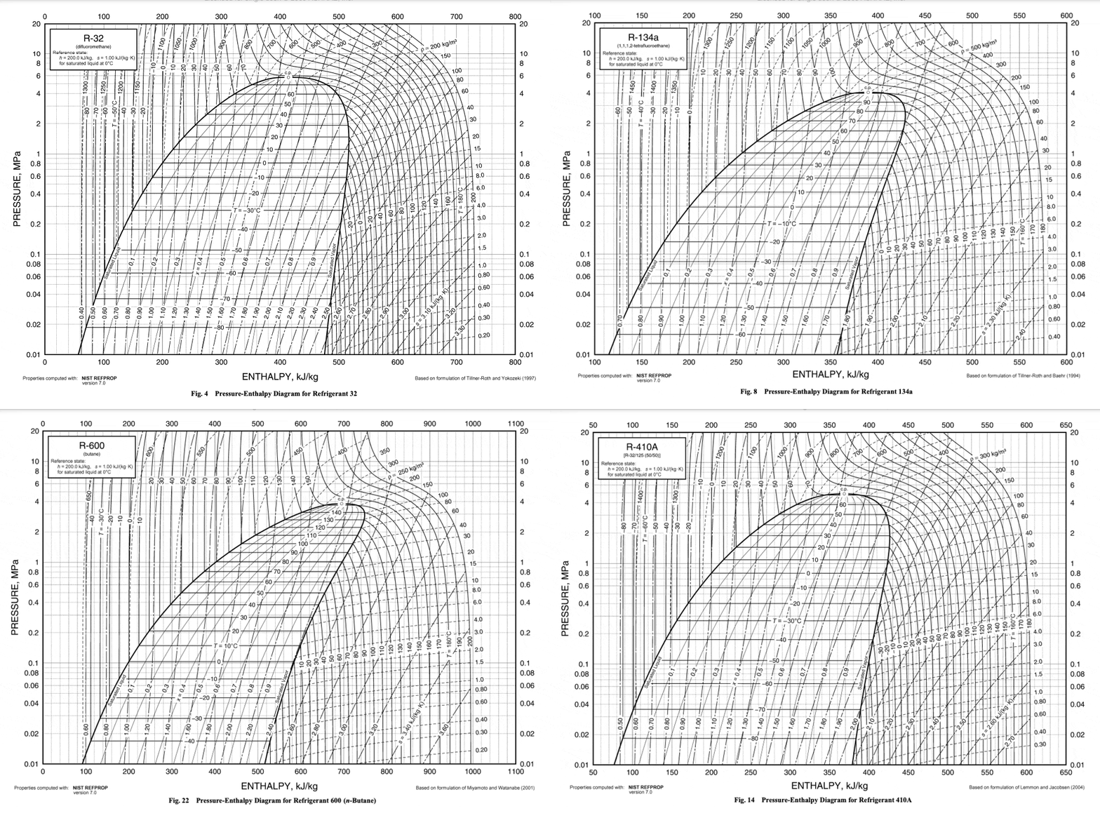
Behaviors of gaseous refrigerants in response to energy, pressure, volume, and temperature change can be calculated with variations on the First Law of Thermodynamics and the Ideal Gas Law. Each refrigerant has a unique set of responses to these changes once phase change is taken into account. These are encompassed in each refrigerant’s Pressure-Enthalpy (P-H) diagram.


Source for all base P-H diagrams: ASHRAE Handbook 2009, Chapter 30
These swirly charts of eddies and vortexes may seem to be jumbles of information difficult to digest. But they really are a lovely way to keep track of what changes in pressure and enthalpy mean for a substance’s temperature and vaporization.
Each point on the chart represents a certain pressure and enthalpy of the refrigerant. The lines on the chart represent a sort of topography of values so that at any one of those pressure-enthalpy points, one can also find the refrigerant’s corresponding temperature and vaporization level.
All four of these characteristics relate to a refrigerant’s “energy.” In a heat pump, an increase in pressure increases the total energy of the system, but also causes some energy already in the system that was exhibited as vaporization to be exhibited as temperature, instead. This is what causes the refrigerant to become hotter than expected.
First, some definitions:
Liquid-Vapor Mix Region: the region where a substance is a mixture of liquid and vapor. On the left of the region, the substance is completely liquidized; on the right, it is completely vaporized. Vapor content gets higher along the x-axis. The top of this region is the Critical Point, where things are wonky and the vapor and liquid phases of a substance are virtually the same.
Pressure (megapascals): marked on the y-axis. Describes how much stress is within the system. Pressure can be increased by doing work on, or adding energy to, the system, and can be decreased when the system does work on something else. (Work is defined as the transfer of energy from one object to another through the application of a force.)
Enthalpy (kilojoules per kilogram): marked on the x-axis. A measure of the total energy in a system. Enthalpy is equal to the system’s internal energy plus the product of its volume and pressure.
Temperature (degrees Celsius): temperature measures the kinetic energy of a substance’s particles. It usually increases with enthalpy, but not when a substance is changing state; through the liquid-vapor mix region, the lines are horizontal because increases in enthalpy go towards vaporizing the substance, rather than increasing its temperature.
Entropy/Vaporization (kilojoules per degree Celsius): represented by the verticalish lines on the chart. In this context, entropy can be described as how vaporized, or disordered, the liquid-vapor mixture is. The thermodynamic identity shows that the internal energy of a substance is related to a temperature entropy term and a pressure volume term. This means that if pressure and volume remain constant, an increase in a system’s internal energy is distributed between a temperature increase and an entropy increase. (Enthalpy, as detailed above, incorporates this internal energy.)
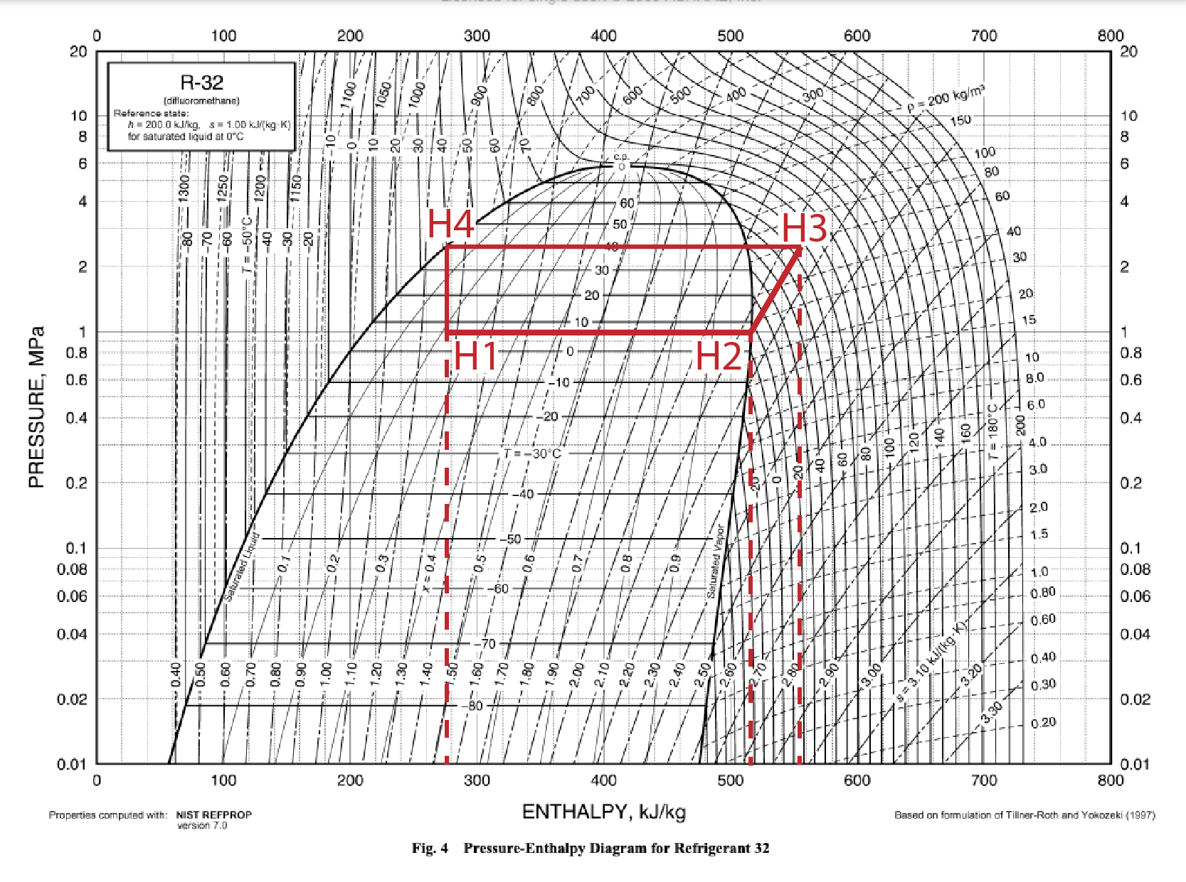
A heat pump cycle can be drawn on the P-H diagram by illustrating which of these characteristics are changed with each step in the cycle.
Expansion Device: an adiabatic (constant enthalpy) process. The system’s pressure and temperature are lowered as the refrigerant does work on the device, but its enthalpy remains the same due to the increase in volume. This leaves the refrigerant at a temperature colder than the cool air outside.
Evaporator: an isothermal (constant temperature) and isobaric (constant pressure) process. Heat energy from the outside air is transferred to the refrigerant, but the temperature of the refrigerant does not change. This energy transfer results in vaporization.
Compressor: an isentropic (constant entropy) process. Work that is put into the system goes only towards increasing its pressure and enthalpy. The amount of increase of each is dictated by the slope of the constant entropy line and the starting and ending pressure of the compressor. Because this happens at the border of the liquid-vapor mix region, some of the energy that used to be contributing to vaporization is exhibited as heat, increasing the temperature of the refrigerant to be hotter than the hot air inside.
Condenser: an isothermal and isobaric process. Heat energy transfers from the refrigerant to the inside air, but this energy is coming from a phase change, rather than temperature decrease.
Note: this is an idealized version of a heat pump cycle. In reality, there are variations within each of these processes and other types of energy transfer to the environment in places.
Another Note: it is possible to superheat and sub-cool a refrigerant by continuing temperature transfer past the boundary of the vapor-mix region. However, this is not usually a way to increase efficiency, as the compression and expansion processes are most often optimized at the vapor-mix region boundary.
Last Note: different heat pumps have slightly different starting and ending pressures, even with the same refrigerant. The cycle shown here uses pressure values that are an average of several commercial R-32 heat pumps. This paper has some very cool graphics showing how the shape of the cycle changes between different refrigerants. For the most part, they follow this general pattern.
700%

A heat pump’s coefficient of performance is a measure of the amount of heat that it moves per unit of work done by the compressor. This calculation assumes an impossibly ideal situation, in which no energy is lost to the environment, but is useful to illustrate how heat pumps work their ultra-efficient magic.
coefficient of performance = Qh/W,
where Qh is the difference in enthalpy between the beginning and end of the condenser stage:
Qh = H3-H4 = 555-275 = 280 kJ/kg,
and the work done by the compressor is the difference in enthalpy between the beginning and end of the compressor stage:
W = H3-H2 = 555-515 = 40 kJ/kg.
This yields:
Qh/W = 280/40 = 7,
meaning the pump moves 7 times as many kJ of energy as it requires to run!
In real-world situations, heat pumps are not perfect, losing energy to the environment. This can be measured empirically with temperature and circuit data, and usually results in a coefficient of performance between 2.5 and 4.
This is still an efficiency of 250-400%. Natural gas furnaces, for comparison, convert around 90% of the energy within the gas to useful heat, never topping 100%.
The End
So there you have it. Heat transfer cycles. Snippets of the complexity behind your friendly temperature control system.
Heating and cooling systems are still on the up and up. In coming years, they will grow in efficiency and versatility in new buildings, in old buildings, in heavy industry, in food distribution, you name it, especially as more stringent energy and emissions codes are implemented.
I hope you see how cool they are. If not, I’d check to see if your refrigerator is running.
